Jul 21, 2014 0 Comments in I2C, Learning, Peripheral, Sensor by
Managing the I2C sensors board PICkit

This product can be bought at our shop as:

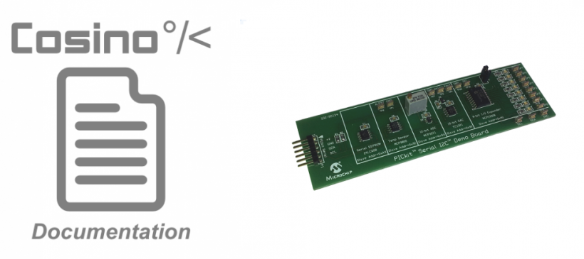
By using the I2C bus you may get access to a wide set of sensors and/or IOs ports, and this simple demo board allows you to play with different devices whose can be very useful in a lot of embedded industrial applications.

By using this board you can have, at once, an EEPROM, a temperature sensor, a 12-bit ADC, a 10-bit DAC and a 8-bit IO expander.

Connecting the device

In order to get access to the device you need to should consider the table below.

Mega 2560 extension

Signal J19
N.C.
+V 5
GND 33
SDA 21
SCL 25
N.C.

See the board’s data sheet here for further info.

Getting access to the device

In order to get access to the device from the user space you can use the i2c-dev module which allows you to access to any I2C devices in raw mode. Of course, this is NOT the only way to get access to these devices! This is definitely the hard way to do it. Fortunately we can use dedicated drivers whose will simplify you life.

warning Note: currently there a no dedicated driver for for the DAC (TC1321) but using this device is so simple that you can forget about it.

As first step, and in order to check if all connections have been done correctly, let’s use the i2c-dev module and the i2c-tools!

warning Note: The i2c-tools are ready to use on the preconfigured microSD card. If you are using your own card you have to install the package before using it.

First of all we must load the module:

then we can use the i2cdetect command to detect all I2C devices on the board:

As you can see in the command output you can find all devices at their I2C slave addresses as reported on product page (warning: considering the addresses on 7 bits only! On the product page the I2C addresses are on 8 bits).

Installing the I2C drivers

Now let’s see how we can add a proper driver for each device in order to simplify its management.

warning Note: remember that the DAC TC1321 has not a driver so it is not reported into this list.

For the auto-loading of all I2C drivers you must patch the Linux DTS file as follow:

warning Note: this example is referred to the Cosino Mega 2560 board so you should modify your DTS file according to your board settings.

Now just recompile the kernel and reboot the system.

The EEPROM

The EEPROM can now be accessed by using the file:

and you can now use it as a normal file:

# echo "Testing string" > /sys/class/i2c-adapter/i2c-0/0-0050/eeprom
# cat /sys/class/i2c-adapter/i2c-0/0-0050/eeprom | strings
Testing string

warning Note: command strings has been used in order to discard all non ASCII chars due the fact the cat command will read all the EEPROM content!

The temperature sensor

The temperature can be easily read by using:

# cat /sys/class/i2c-adapter/i2c-0/0-0049/temp1_input
28687
The output data are in m°C.

The ADC

The ADC can be easily accessed by using:

# cat /sys/class/i2c-adapter/i2c-0/0-004d/in0_input
2087

The IO Expander

The IO expander is exported into the system as several GPIOs lines all connected to a gpiochip:

# cat /sys/class/gpio/gpiochip248/label
mcp23008

Now you have 8 new GPIOs lines as stated by the driver:

# cat /sys/class/gpio/gpiochip248/ngpio
8

For example, you can get access to the IO expander first GPIO line by exporting it according to the gpiochip base number:

# cat /sys/class/gpio/gpiochip248/base
248
root@cosino:~# echo 248 > /sys/class/gpio/export

By default the new GPIO line is an input:

# cat /sys/class/gpio/gpio248/direction
in

but you can turn it into an output by using:

# echo out > /sys/class/gpio/gpio248/direction

Now, if you set the output high, you can do it by using the command:

# echo 1 > /sys/class/gpio/gpio248/value

the led DS1 on the board will turn on.

Facebooktwitterlinkedin
Tags:

Leave a Reply

Your email address will not be published. Required fields are marked *

+ 54 = 64